-
Feature
-
Interface
-
File Operation
-
Design Central
-
Basic Setting
-
Viewing Tools
-
Object Operation
-
Drawing
-
Parametric
-
Graph Editing
-
Graph Transform
- Move
- rotate
- Transform Again
- Mirror
- Arc and Line Fit
- Envelop Distortion
- Perspective Distortion
- Push and Pull Distortion
- Twist Distortion
- Shadow Distortion
- Curve Zmap
- Interactive Nesting
- Auto Nesting
- Clone Along a Curve
- Rectangular Clone&Polar Clone
- Clone along a Line
- Clone along an Arc
- Clone along a Spiral
- Scale 2 Points
- Orient 2 lines
- 3D Move
- 3D Rotate
- 3D Scale
- 3D To XY Plane
-
Image Processing
-
Text Editing
-
Node Editing
-
Graph Toolpath
- Tool Path
- Profile Machining
- Area Clearance
- Flute Machining
- 3D Corner Engraving
- Midine Machining
- Drilling
- Insert And Inlay
- Intelligent Machining
- Prism Machining
- Embossing Machining
- Toolpath output
- Tool Management
- Toolpath Walk Simulation
- Toolpath Shaded Simulation
- Post Set
- Toolpath Regenerate
- Toolpath Stat
- Adaptive Area Clearance
- Chamfer Machining
-
Image Toolpath
-
Wireframe Toolpath
-
Toolpath Edit
-
Waveboard
-
Relief
-
Surface
-
Surface Toolpath
Sweep Surface
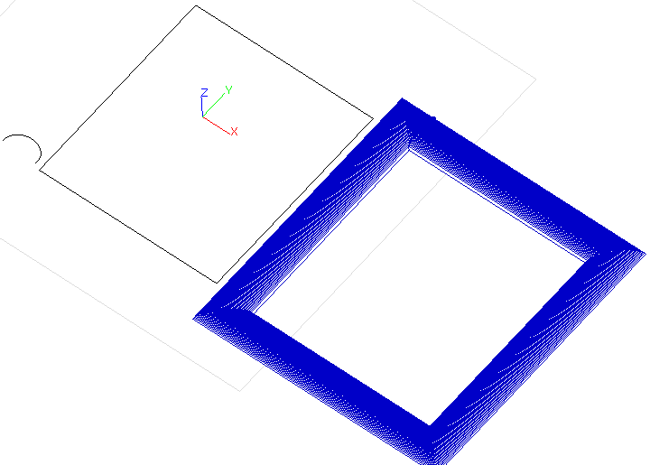
A cross section will be swept around the drive rail to create the sweep surface. The cross section needs to be an open shape in order for this to work.
As follow fig: Arc is the cross section curve , Rect is the driver rail curve.


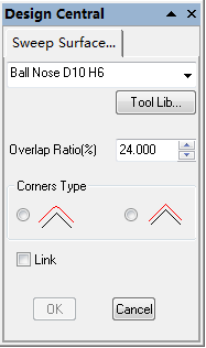
Overlap Ratio: The ratio of the width of bootom blade to the width of the previous toolpath.
The value is smaller, in most situations this will improve the finish quality but also potentially increase the machining time.
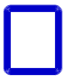
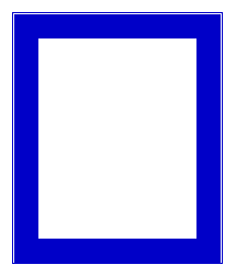
Corner Type: when the driver rail has sharp corners. this item is valid.
Round Corner.

Sharp corner

Link:link the neighbor toolpath so that the tool can move continually。
1.Pick the driver rail curve.
2.Pick the cross section curve.
3.Click OK button to create the toolpath.
Remark:
1.if pick the selected curves again, it refer to reverse the direction of the curve
2.The arrows and green square on the cross section indicate the direction and the start point. The start point of the cross section will be attached to the start point of the drive rail.
3. On a closed drive rail, the cross section curve will always be “hung” on the outside of the rail, it is not possible to change this to the inside. Reversing the closed drive rail curve, will change the direction that the toolpath is created in.
