Welcome to Ucancam Knowledge Base
-
Feature
-
Interface
-
File Operation
-
Design Central
-
Basic Setting
-
Viewing Tools
-
Object Operation
-
Drawing
-
Parametric
-
Graph Editing
-
Graph Transform
- Move
- rotate
- Transform Again
- Mirror
- Arc and Line Fit
- Envelop Distortion
- Perspective Distortion
- Push and Pull Distortion
- Twist Distortion
- Shadow Distortion
- Curve Zmap
- Interactive Nesting
- Auto Nesting
- Clone Along a Curve
- Rectangular Clone&Polar Clone
- Clone along a Line
- Clone along an Arc
- Clone along a Spiral
- Scale 2 Points
- Orient 2 lines
- 3D Move
- 3D Rotate
- 3D Scale
- 3D To XY Plane
-
Image Processing
-
Text Editing
-
Node Editing
-
Graph Toolpath
- Tool Path
- Profile Machining
- Area Clearance
- Flute Machining
- 3D Corner Engraving
- Midine Machining
- Drilling
- Insert And Inlay
- Intelligent Machining
- Prism Machining
- Embossing Machining
- Toolpath output
- Tool Management
- Toolpath Walk Simulation
- Toolpath Shaded Simulation
- Post Set
- Toolpath Regenerate
- Toolpath Stat
- Adaptive Area Clearance
- Chamfer Machining
-
Image Toolpath
-
Wireframe Toolpath
-
Toolpath Edit
-
Waveboard
-
Relief
-
Surface
-
Surface Toolpath
Category
< All Theme
Print
Image FM Machining
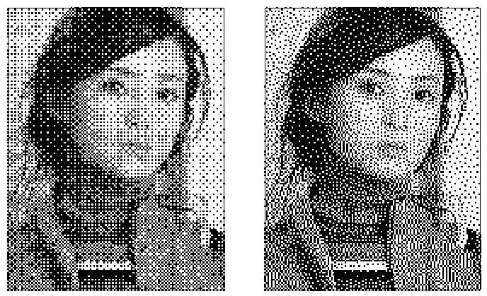
Image FM machining is to engrave the object after the image is converted into grayscale image. It is to make the depth of the dots the same while the distance between the dots is different.
Command:
Menu【Toolpath > Image Machining > Image FM Machining】

Steps:
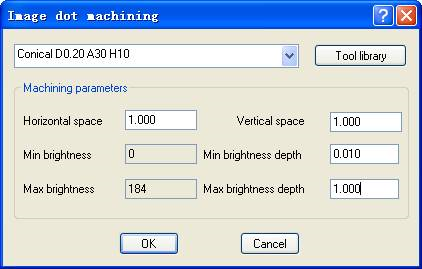
1. Select the objects .2. ClickMenu【Toolpath > Image Machining > Image FM Machining】 .
3. Set the parameters, Click OK button.
Parameters:
1)Dither: to make the surface of processed image seems smoother.
2)Diffuse: is to highlight the details
3)Resolution: the minimum distance between two points.
4)Depth: the depth of milling.

