Tip: Start typing in the input box for immediate search results.
-
Feature
-
Interface
-
File Operation
-
Design Central
-
Basic Setting
-
Viewing Tools
-
Object Operation
-
Drawing
-
Parametric
-
Graph Editing
-
Graph Transform
- Move
- rotate
- Transform Again
- Mirror
- Arc and Line Fit
- Envelop Distortion
- Perspective Distortion
- Push and Pull Distortion
- Twist Distortion
- Shadow Distortion
- Curve Zmap
- Auto Nesting
- Interactive Nesting
- Clone Along a Curve
- Rectangular Clone&Polar Clone
- Clone along a Line
- Clone along an Arc
- Clone along a Spiral
- Scale 2 Points
- Orient 2 lines
- 3D Move
- 3D Rotate
- 3D Scale
- 3D To XY Plane
-
Image Processing
-
Text Editing
-
Node Editing
-
Graph Toolpath
- Tool Path
- Profile Machining
- Area Clearance
- Flute Machining
- 3D Corner Engraving
- Midine Machining
- Drilling
- Insert And Inlay
- Intelligent Machining
- Prism Machining
- Embossing Machining
- Toolpath output
- Tool Management
- Toolpath Walk Simulation
- Toolpath Shaded Simulation
- Post Set
- Toolpath Regenerate
- Toolpath Stat
- Chamfer Machining
- Adaptive Area Clearance
-
Image Toolpath
-
Wireframe Toolpath
-
Toolpath Edit
-
Waveboard
-
Mesh
-
Relief Sculpt
-
Surface
- Surface
- Import Surface File
- Standard Surface
- Freeform Surface
- Chamfer Surface
- Fillet Surface
- Extend Surface
- Show Effect
- To 3D Curve
- Curve Project to Surface
- Pullback
- Extract Edge
- Split at Isocurve
- Trim at Curve
- Trim at Surface
- Untrim
- To Mesh
- Edit Node of Surface
- Insert Control Point
- Vari Fillet Surfaces
- 3D-Spline
- Surface Flatten
- Mesh Wrap
-
Canvas 3D
-
Surface Toolpath
Insert And Inlay
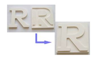
Inserted and inlayed moulds are made by profile machining and area clearance.

Command:
Menu【Toolpath > Insert and Inlay >Insert Machining】 Toolpath Bar
MenuToolpath > Insert and Inlay > Inlay Machining Toolpath Bar


Steps:
1. Select the objects.
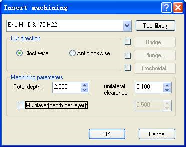
2. Click Menu【Toolpath > Insert and Inlay >Insert Machining】.
3. Set the parameters, Click OK button.
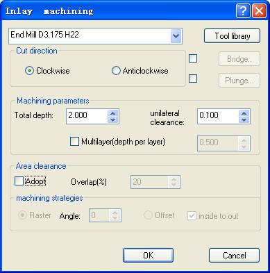
4. Click Menu【Toolpath > Insert and Inlay > Inlay Machining】.
5. Set the parameters, Click OK button.
Parameters: please refer to the Profile Machining and Area Clearance.
Unilateral clearance: the distance between the inlayed mould and the inserted mould, This parameter is given in both Inlay and Insert, and you need only input one value.
