Profile Machining
Profile Machining is widely used for cutting.

Command:
Menu【Toolpath >Profile Machining】 Toolpath Bar
Steps:
1. Select the object.
2. ClickMenu【Toolpath >Profile Machining】.
3. Set the parameters.
4. Click OK button, creates the toolpath.
Parameters:
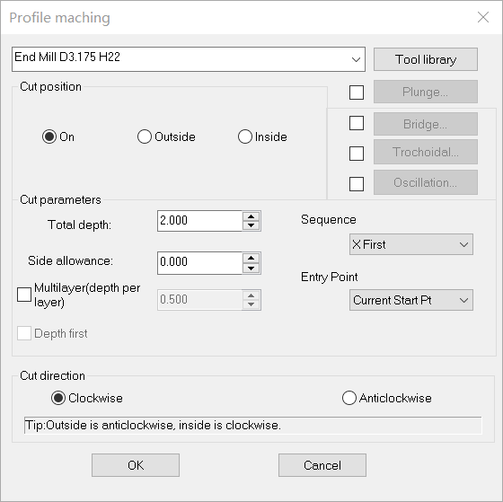
1)Tool library: You can choose a tool from the drop-down list of tool library or click Tool Library button to choose.

2)Cut position:
on outside inside
On: The tool center axis is along the original drawing.
Outside: Cut along the outer contour of the drawing.
Inside: Cut along the inner contour of the drawing.
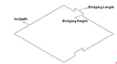
3)Bridge: In order to prevent the machined object from moving which may cause objects to be destroyed or machining errors, the machined object had better not be completely separated from the material before the machining is finished. After machining, the object can be separated from the material by hand.
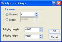
4)Plunge: There are 3 ways to plunge.
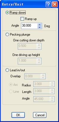
1. Ramp
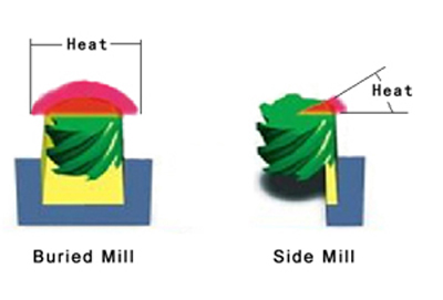
To plunge in a certain angle. tools will not be destroyed or broken because of the force during entering material.This also ensures that no mark or scar is left on the surface of the material. If check the “ramp up”, the tool will retract in slanting direction to ensure the seperation between the part and stock , even if the stock is deforming.

2. Pecking plunge
When using Pecking plunge, the tool goes into a certain depth into the material, and then goes up to a certain height, and repeat this process when cutting the material. Pecking plunge prevents the tool breaks especially when cutting hard materials.

3. Lead in /out
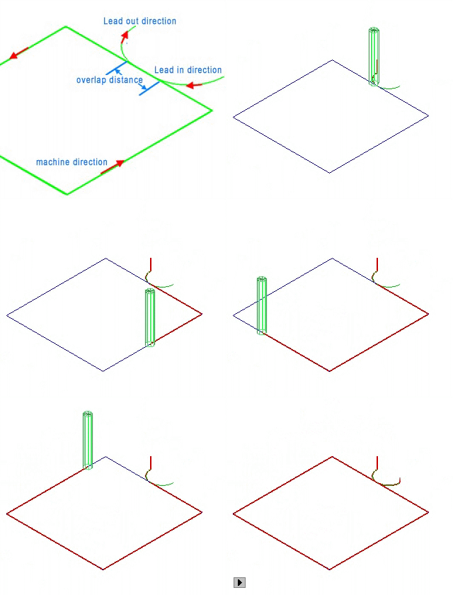
The tool first goes into a certain depth outside of the material, and then cuts into the side of the material.
REMARK: Bridge and Plunge can not be activated at the same time.
There are two type of trochoidal rotation: The full-circle motion is ideal for high speed machining , the half-circle may be more appropriate for traditional cutting at lower speeds (due to less motion).
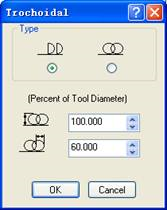
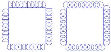
Parameter settings half-circle full-circle
6)Oscillation: The difference with traditional machining is that the tool is cutting materals along both the X,Y plane and the Z axis direction,which makes full use of and protects the tool and improve the effiency of cutting.
Linear type:
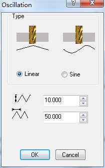
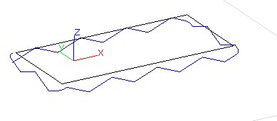
parameter setting of Linear type 3D view of Linear type
Sine type:
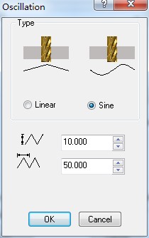
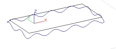
parameter setting of Sine type 3D view of Sine type
7)Total depth: the machining depth.
8)Side allowance: the area outside the Toolpath. Precision cutting can be achieved through setting side allowance
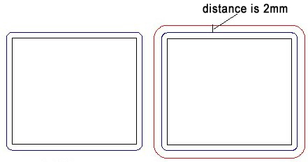
allowance is 0 allowance is 2mm
9)Sequence:
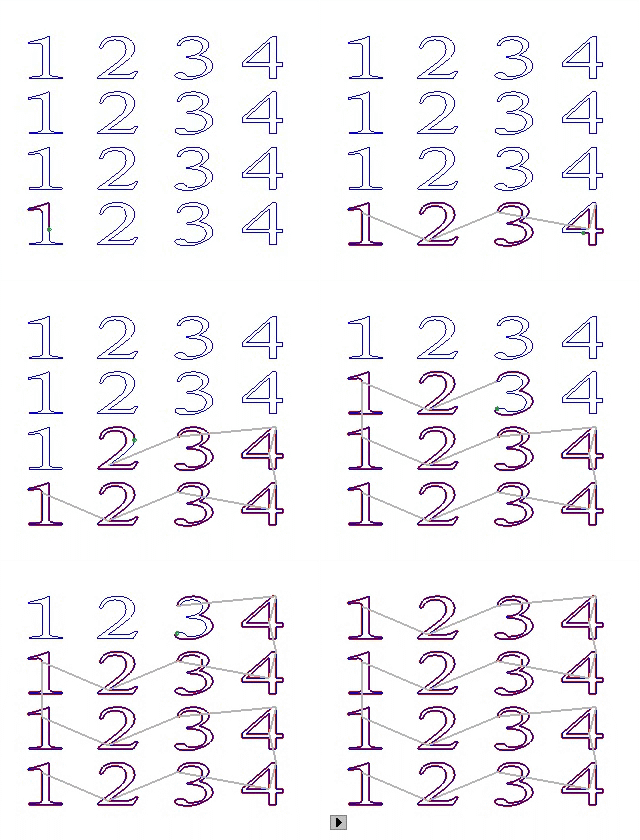

X First YFirst
Near First: the nearest object to the tool will be machined first.
X/Y First: machine objects along X/Y axis direction first.
10)Entry Point: include :Current Start Point , and the feature Point of the object box : Left Bottom 、Left Top、Right Bottom 、Right Top、Left Middle 、Right Middle、Top middle、Bottom middle。
11)Multi layer: When the depth of the material is bigger than the tool height or when the material is of high rigidity (such as metal), the machining is done layer by layer on the material.
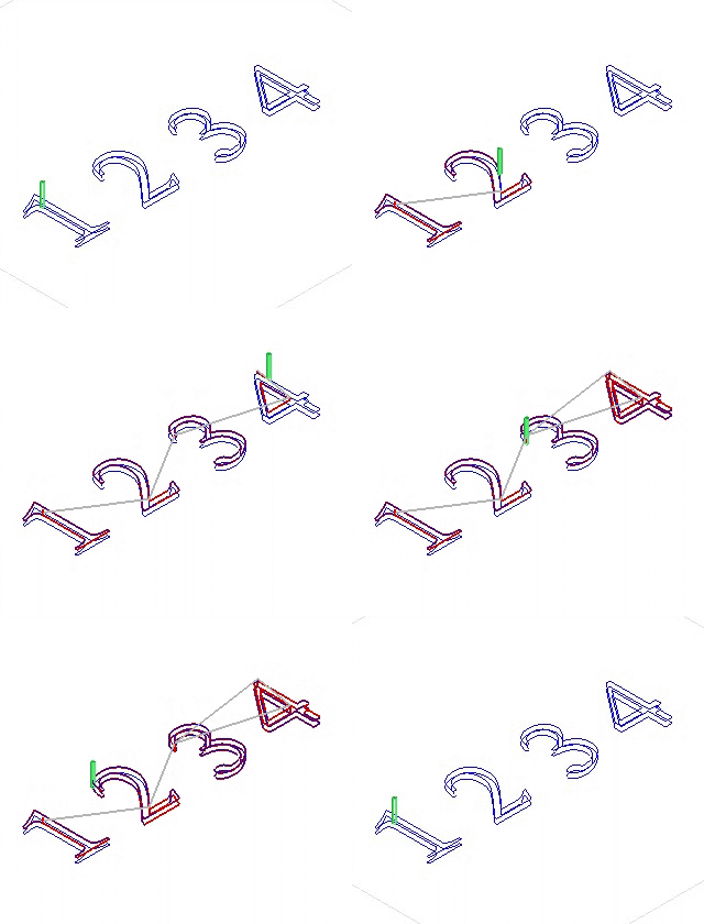

layer first Depth first
Depth first: machine next object after finishing machine all the layers of one object.
12)Cut direction: is the direction of the toolpath, including clockwise and anti-clockwise. When choosing cutting direction, the material should be taken into consideration so that the surface of the material after being machined is smooth. Clockwise machining is fit for cutting materials of high density, such as Acryl (organic glass), brass, etc; anti-clockwise machining is fit for cutting materials of low density such as PVC board, two-color board, etc.
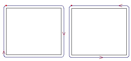
clockwise anti-clockwise
